Difference between revisions of "Dzenushko Dainis: Walking mechanisms survey"
(Created page with "Существует несколько основных видов «шагающих» механизмов, основанных на преобразовании враща...") |
|||
| Line 1: | Line 1: | ||
| − | + | There are several basic types of "walking" | |
| − | + | mechanisms based on conversion of the | |
| − | + | rotational motion into the translational motion. | |
| − | |||
---- | ---- | ||
| − | == | + | ==Chebyshev Walking Mechanism== |
<gallery widths=330px heights=300px perrow = 3> | <gallery widths=330px heights=300px perrow = 3> | ||
File:stopohodjashaja_mashina_1.jpg | File:stopohodjashaja_mashina_1.jpg | ||
| Line 11: | Line 10: | ||
File:stopohodjashaja_mashina_3.jpg | File:stopohodjashaja_mashina_3.jpg | ||
</gallery> | </gallery> | ||
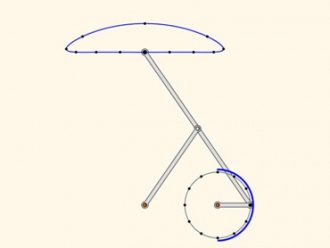
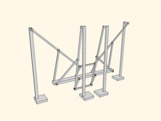
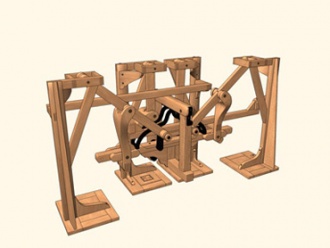
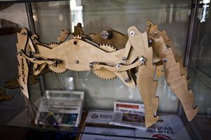
| − | * | + | *Pafnuty Lvovich Chebyshev, the professor of St. Petersburg University invented and built the world's first walking mechanism and named it "The Plantigrade Machine". This mechanism, invented by Russian mathematician, has received the general approval at the World Exhibition in Paris, 1878. |
| − | |||
| − | |||
| − | |||
---- | ---- | ||
| − | == | + | ==Klann Mechanism== |
[[File:Klann_1.png]] | [[File:Klann_1.png]] | ||
| Line 24: | Line 20: | ||
[[File:Klann_3.gif]] | [[File:Klann_3.gif]] | ||
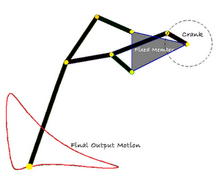
| − | * | + | *The Klann linkage provides many of the benefits of more advanced walking vehicles without some of their limitations. It can step over curbs, climb stairs, or travel into areas that are currently not accessible with wheels but does not require microprocessor control or multitudes of actuator mechanisms. It fits into the technological space between these walking devices and axle-driven wheels. |
| − | |||
| − | |||
| − | |||
| − | |||
| − | |||
| − | |||
| − | |||
| − | |||
---- | ---- | ||
| Line 42: | Line 30: | ||
File:Jansen_3.jpg | File:Jansen_3.jpg | ||
</gallery> | </gallery> | ||
| − | |||
| − | |||
| − | |||
| − | |||
| − | |||
| + | *Theo Jansen (born 1948) is a Dutch artist. In 1990, he began what he is known for today: building large mechanisms out of PVC that are able to move on their own, known only as Strandbeest. Jansen has been creating Strandbeest (Dutch: strand=beach; beest=beast), wind-walking examples of artificial life, since 1990. What was at first a rudimentary breed has slowly evolved into a generation of machines that are able to react to their environment: "over time, these skeletons have become increasingly better at surviving the elements such as storms and water, and eventually I want to put these animals out in herds on the beaches, so they will live their own lives." | ||
http://www.strandbeest.com/ | http://www.strandbeest.com/ | ||
| Line 56: | Line 40: | ||
</gallery> | </gallery> | ||
| − | == | + | ==Creating a self-propelled platform based on the mechanism of Theo Jansen== |
| + | |||
| + | Watching the Theo Jansen mechanisms makes me want to be able to ride on them | ||
| + | (or to "walk"). So, it crossed my mind to create such a device, which could move me | ||
| + | (in a reduced scale, for the beginning). But if we want to ride it, first we need to lern it how to turn. | ||
| + | |||
| + | *How to achieve this? | ||
| + | It is possible to make two independent parts with two independent engines, and by controlling their speed separately turn as well as any crawler does. | ||
| + | |||
| + | *Why this devise is better than a wheeled vehicle? | ||
| + | If you're driving on sand or any loose material, the wheels may start to skid. But the walking mechanisms do not have this problem. | ||
| − | + | *What has been done? | |
| − | + | Currently, the manufacturing process has been developed and debugged. | |
| − | + | ||
| − | + | *How is it done? | |
| − | * | + | This platform is created from plexiglas, aluminum tubes, screws and nuts. In general, they are not that rare materials. The materials were selected on the basis of cheapness, ease of use and aesthetic considerations. But it all started with a sketch of the parts in 1:1 scale. The sketch is reproduced below: |
| − | |||
| − | |||
| − | |||
| − | * | ||
| − | |||
| − | |||
| − | |||
| − | |||
| − | |||
| − | |||
| − | |||
| − | |||
<gallery widths=300px heights=425px perrow = 3> | <gallery widths=300px heights=425px perrow = 3> | ||
| Line 82: | Line 64: | ||
</gallery> | </gallery> | ||
| − | + | Then I had to deal with the first problem of this project - to reduce friction. To cope with it, the simple slide bearings were made from the aluminum tubes: | |
<gallery widths=300px heights=300px perrow = 2> | <gallery widths=300px heights=300px perrow = 2> | ||
File:Roller_1.jpg | File:Roller_1.jpg | ||
| Line 88: | Line 70: | ||
</gallery> | </gallery> | ||
| − | + | After the first assembly I realised that it is not so easy to align the crankshaft. This problem was solved by threading it on the rods, this allowed me to align the central axis at the final assembly. And here is the first photos of the second part during the assembly proccess. It is possible to see all the six rods going through the entire mechanism: | |
| − | |||
| − | |||
<gallery widths=500px heights=280px perrow = 2> | <gallery widths=500px heights=280px perrow = 2> | ||
File:Build2_1.jpg | File:Build2_1.jpg | ||
| Line 96: | Line 76: | ||
</gallery> | </gallery> | ||
| − | + | Here's how the first part looks like: | |
<gallery widths=500px heights=400px perrow = 2> | <gallery widths=500px heights=400px perrow = 2> | ||
File:Build_1.jpg | File:Build_1.jpg | ||
| Line 104: | Line 84: | ||
</gallery> | </gallery> | ||
| − | == | + | ==What is planned next?== |
| − | 1) | + | 1) make the second part (DONE) |
| − | 2) | + | 2) combine them (DONE) |
| − | 3) | + | 3) mount engines(DONE) |
| − | 4) | + | 4) create a controll system (DONE) |
| − | 5) | + | 5) create and install a remote control |
| − | 06.10.11 | + | 06.10.11 at 23:58 the first successful launch of the combined mechanism has been performed |
| − | + | Now the wired control system is set up. | |
| − | + | So that's what we have: | |
<gallery widths=900px heights=400px perrow = 1> | <gallery widths=900px heights=400px perrow = 1> | ||
File:IMAG0758.jpg | File:IMAG0758.jpg | ||
</gallery> | </gallery> | ||
| − | == | + | ==Walking mechanism 1.2== |
[[File:intensiv.jpg |300px|right]] | [[File:intensiv.jpg |300px|right]] | ||
На летнем интенсиве[http://fablab.spbstu.ru/2013/06/post750/] для школьников в Фаблаб Полдитех, проходившем в конце июня 2013 года под руководством [http://tm.spbstu.ru/%D0%9C%D1%83%D1%80%D0%B0%D1%87%D1%91%D0%B2_%D0%90%D0%BD%D0%B4%D1%80%D0%B5%D0%B9 Андрея Мурачёва] и [http://tm.spbstu.ru/%D0%94%D0%B7%D0%B5%D0%BD%D1%83%D1%88%D0%BA%D0%BE_%D0%94%D0%B0%D0%B9%D0%BD%D0%B8%D1%81 Дайниса Дзенушко] был собран шагающий механизм на основе платформы Arduino. Управление Arduino осуществлялось с компьютера при помощи среды Processing. Программы для Arduino и Processing можно скачать по ссылке [[File:Proc_and_ardu.zip]] | На летнем интенсиве[http://fablab.spbstu.ru/2013/06/post750/] для школьников в Фаблаб Полдитех, проходившем в конце июня 2013 года под руководством [http://tm.spbstu.ru/%D0%9C%D1%83%D1%80%D0%B0%D1%87%D1%91%D0%B2_%D0%90%D0%BD%D0%B4%D1%80%D0%B5%D0%B9 Андрея Мурачёва] и [http://tm.spbstu.ru/%D0%94%D0%B7%D0%B5%D0%BD%D1%83%D1%88%D0%BA%D0%BE_%D0%94%D0%B0%D0%B9%D0%BD%D0%B8%D1%81 Дайниса Дзенушко] был собран шагающий механизм на основе платформы Arduino. Управление Arduino осуществлялось с компьютера при помощи среды Processing. Программы для Arduino и Processing можно скачать по ссылке [[File:Proc_and_ardu.zip]] | ||
| − | == | + | The next walking mechanism, now based on the Arduino platform, was assembled during the [http://fablab.spbstu.ru/2013/06/post750/ Summer Crash Course] for pupils in Fablab Polytech held at the end of June 2013 under the supervision of [[:ru:Andrey_Murachev|Andrey Murachev]] and [[:ru:Dzenushko_Dainis|Dainis Dzenushko]]. The Arduino board control was performed from a computer using the Processing development tool. The program code for Arduino and Processing can be downloaded [[File:Proc_and_ardu.zip|here]]. |
| + | |||
| + | == See also == | ||
| − | [[:ru:Ходящие механизмы]] | + | [[:ru:Ходящие механизмы|Walking mechanisms]] |
| − | [[:ru:Category: Студенческие проекты]] | + | [[:ru:Category: Студенческие проекты|Category: Student projects]] |
Revision as of 08:25, 30 June 2014
There are several basic types of "walking" mechanisms based on conversion of the rotational motion into the translational motion.
Contents
Chebyshev Walking Mechanism
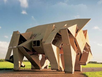
- Pafnuty Lvovich Chebyshev, the professor of St. Petersburg University invented and built the world's first walking mechanism and named it "The Plantigrade Machine". This mechanism, invented by Russian mathematician, has received the general approval at the World Exhibition in Paris, 1878.
Klann Mechanism
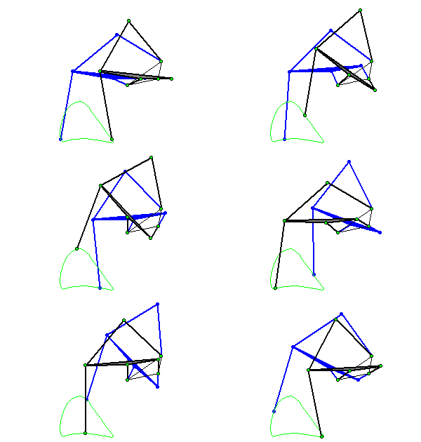
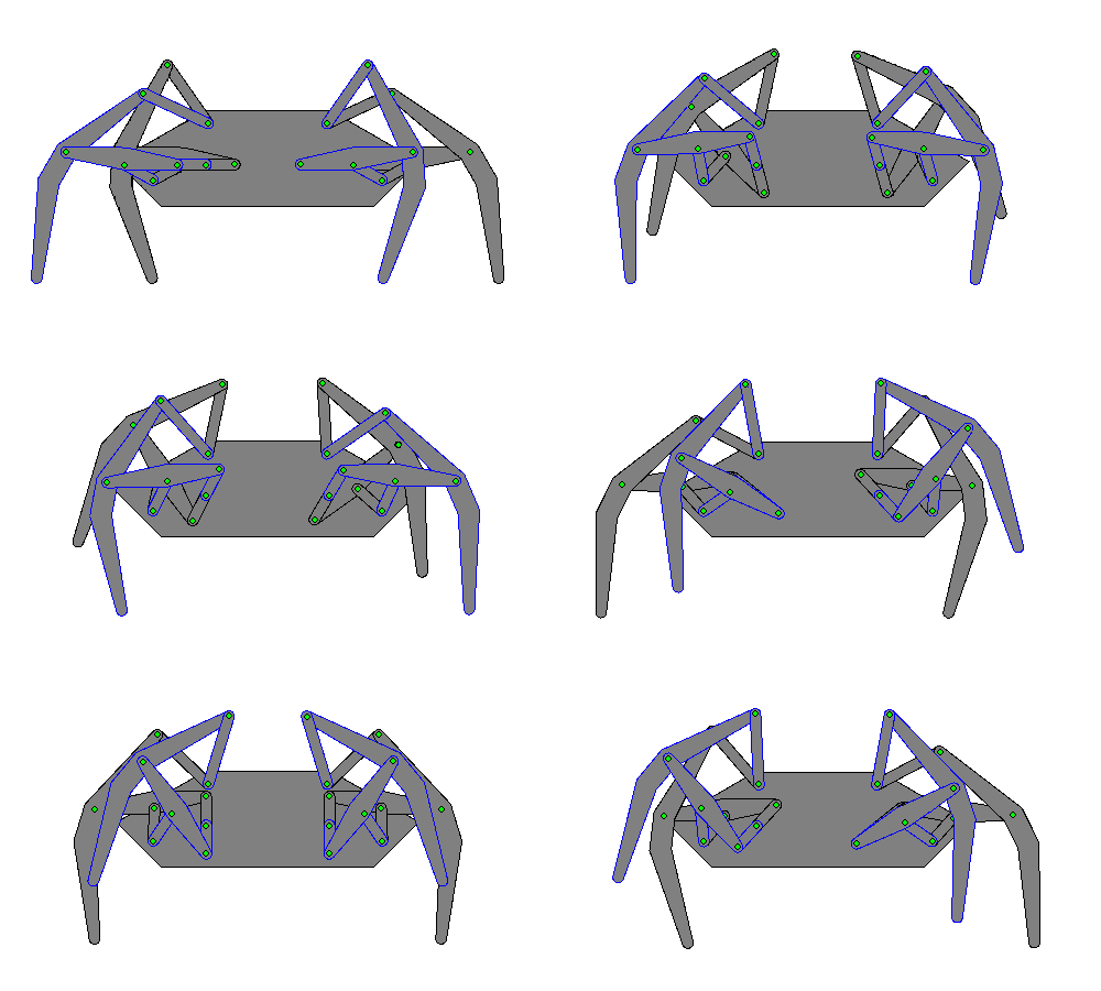
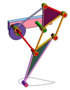
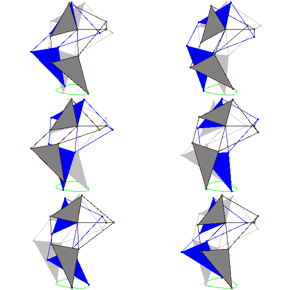
- The Klann linkage provides many of the benefits of more advanced walking vehicles without some of their limitations. It can step over curbs, climb stairs, or travel into areas that are currently not accessible with wheels but does not require microprocessor control or multitudes of actuator mechanisms. It fits into the technological space between these walking devices and axle-driven wheels.
Механизм Тео Янсена
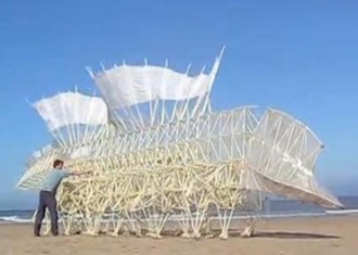
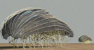
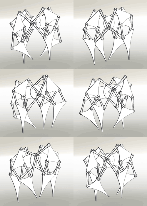
- Theo Jansen (born 1948) is a Dutch artist. In 1990, he began what he is known for today: building large mechanisms out of PVC that are able to move on their own, known only as Strandbeest. Jansen has been creating Strandbeest (Dutch: strand=beach; beest=beast), wind-walking examples of artificial life, since 1990. What was at first a rudimentary breed has slowly evolved into a generation of machines that are able to react to their environment: "over time, these skeletons have become increasingly better at surviving the elements such as storms and water, and eventually I want to put these animals out in herds on the beaches, so they will live their own lives."
Creating a self-propelled platform based on the mechanism of Theo Jansen
Watching the Theo Jansen mechanisms makes me want to be able to ride on them (or to "walk"). So, it crossed my mind to create such a device, which could move me (in a reduced scale, for the beginning). But if we want to ride it, first we need to lern it how to turn.
- How to achieve this?
It is possible to make two independent parts with two independent engines, and by controlling their speed separately turn as well as any crawler does.
- Why this devise is better than a wheeled vehicle?
If you're driving on sand or any loose material, the wheels may start to skid. But the walking mechanisms do not have this problem.
- What has been done?
Currently, the manufacturing process has been developed and debugged.
- How is it done?
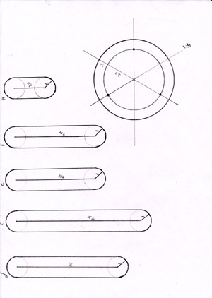
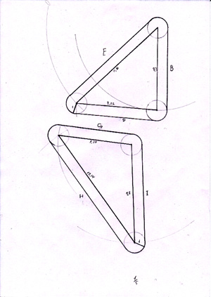
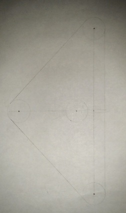
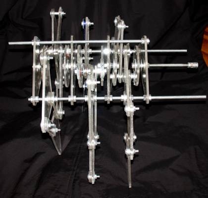
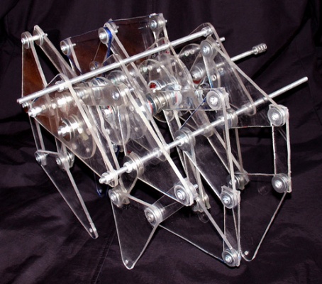
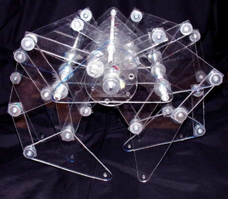
This platform is created from plexiglas, aluminum tubes, screws and nuts. In general, they are not that rare materials. The materials were selected on the basis of cheapness, ease of use and aesthetic considerations. But it all started with a sketch of the parts in 1:1 scale. The sketch is reproduced below:
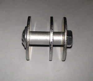
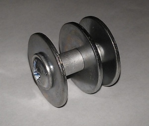
Then I had to deal with the first problem of this project - to reduce friction. To cope with it, the simple slide bearings were made from the aluminum tubes:
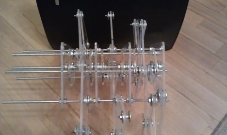
After the first assembly I realised that it is not so easy to align the crankshaft. This problem was solved by threading it on the rods, this allowed me to align the central axis at the final assembly. And here is the first photos of the second part during the assembly proccess. It is possible to see all the six rods going through the entire mechanism:
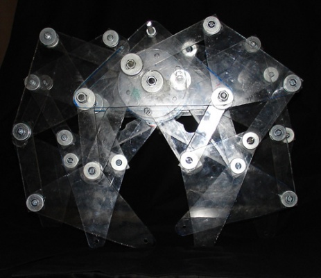
Here's how the first part looks like:
What is planned next?
1) make the second part (DONE)
2) combine them (DONE)
3) mount engines(DONE)
4) create a controll system (DONE)
5) create and install a remote control
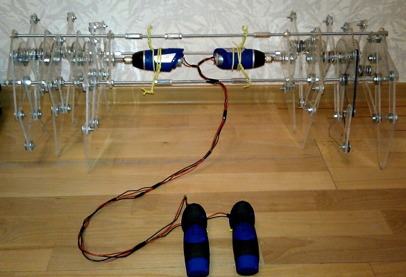
06.10.11 at 23:58 the first successful launch of the combined mechanism has been performed
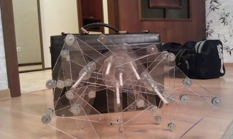
Now the wired control system is set up. So that's what we have:
Walking mechanism 1.2
На летнем интенсиве[1] для школьников в Фаблаб Полдитех, проходившем в конце июня 2013 года под руководством Андрея Мурачёва и Дайниса Дзенушко был собран шагающий механизм на основе платформы Arduino. Управление Arduino осуществлялось с компьютера при помощи среды Processing. Программы для Arduino и Processing можно скачать по ссылке File:Proc and ardu.zip
The next walking mechanism, now based on the Arduino platform, was assembled during the Summer Crash Course for pupils in Fablab Polytech held at the end of June 2013 under the supervision of Andrey Murachev and Dainis Dzenushko. The Arduino board control was performed from a computer using the Processing development tool. The program code for Arduino and Processing can be downloaded File:Proc and ardu.zip.
